
There is a common assumption that micro parts must carry micro tolerances. In practice the reverse is closer to the truth: the tolerance is set by the function, and the difficulty of micro work comes from the ratio between the tolerance and the feature size. A band of ±0.003 mm (milling) / ±0.002 mm (turning) is generous on a 50 mm diameter and demanding on a 1 mm bore, and the measurement of the small feature is where the real challenge lives.
Reading a micro drawing therefore means reading the tolerance against the feature size and the metrology together. A functional micro feature earns a tight band and gets the instrument that can resolve it; a cosmetic micro feature runs at general tolerance like any other. This guide walks that reading — the features that matter, the bands the processes hold, the second processes and finishes, and the verification that closes the loop.

What changes about tolerancing when features get small?
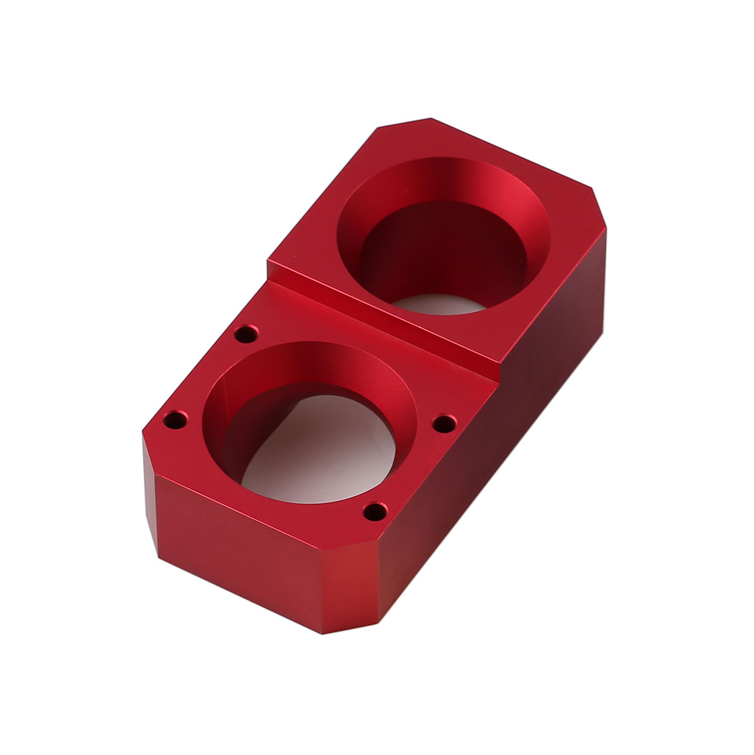
The tolerance band itself does not automatically shrink with the part; what changes is the ratio of tolerance to feature. On a large diameter, ±0.003 mm (milling) / ±0.002 mm (turning) is a fraction of a percent of the size and the process holds it easily. On a small bore, the same band is a larger proportion of the feature, small tools are more sensitive to deflection and wear, and the measurement must resolve a feature that may be near the limit of comfortable handling. The tolerance is the same number, but the engineering behind it is different.
The second change is that the measurement becomes part of the process decision earlier. A buyer tolerancing a micro feature has to ask not only whether the process can hold the band but whether an instrument can verify it, and the instrument choice affects the tolerance's practicality. A feature that cannot be resolved by the shop's CMM or optical system cannot be verified by its report, so the tolerance and the metrology are designed together.
The third change is practical: micro parts are handled, fixtured, and cleaned differently, and the tolerance scheme has to survive that handling. A delicate feature can distort under fixturing pressure; a small part can be lost or damaged in cleaning; a burr in the wrong place can change a fit. The drawing that acknowledges these realities — with edge conditions, handling notes, and realistic bands — is a drawing a micro shop can actually execute.
Which micro features carry the tight bands in practice?
The features that earn tight bands on micro parts are the same kind that earn them on macro parts: the ones that control function. The small bore that locates a mating component, the sealing face that stops a leak, the fine thread that carries a load, and the geometry that the rest of the assembly depends on all justify tight callouts against the datum scheme. The list is short on any drawing, and it should be marked so the inspection knows where the risk sits.
Cosmetic and clearance geometry runs at general tolerance even on micro parts. A cosmetic edge on a tiny housing does not need a precision band; a clearance pocket that has room to spare does not need the shop's finest process. Tightening features that do nothing adds inspection cost without adding function, and on micro parts the inspection is often the dominant cost, so every unnecessary tight callout is doubly expensive.
The discipline is the same as macro work: ask which features would fail the part if they drifted, put the tight bands there, and let the rest breathe. On a micro drawing this selectivity matters more because the inspection list is what drives the price and the schedule. The buyer who marks three functional features and leaves the rest at the block tolerance gets a part that functions and a quote that reflects the real work.
What bands can micro milling and turning hold?
The working bands at micro scale are the same numbers as macro machining: ±0.003 mm (milling) / ±0.002 mm (turning) for milled and turned features, with capability such as Ppk ≥ 1.67 at the initial study on key characteristics and Cpk ≥ 1.33 on general characteristics. Capability is reported per characteristic: every report names the feature, its tolerance band, the sample size, the sigma method, and the study window., and ±0.002 mm where grinding is the process. What differs is the care required to hold them — small tools that deflect and wear faster, fixturing that must hold a tiny part without distortion, and conditions that keep the process stable across a run. The bands are the same; the difficulty is behind them.
The honest conversation at quoting is about which features hold the standard band and which need the extra care. A micro feature at the edge of the standard band may need slower feeds, a fresh tool, or a dedicated setup, and that care is real cost. The quote should distinguish the features that run at normal micro practice from those that need the extra attention, so you can see where the price is going and why.
The process capability claim matters more, not less, at micro scale. A capability figure such as Ppk ≥ 1.67 initial on a micro characteristic says the process holds the band with margin across a run, which is exactly what you needs to plan around. The claim should sit on measurements from the lot or a qualifying run, not on a brochure. A micro shop that can produce the data behind its capability is a shop whose process is real.
When does micro geometry move to grinding or a specialty process?
Some micro requirements exceed what cutting holds economically, and the drawing should route them to the process that can meet them. A tiny journal that must be round in the low microns, a seal seat at a fine finish, or a feature whose cylindricity matters beyond turning belongs to grinding, where the process reaches ±0.002 mm. Routing to grinding is the honest engineering answer, and the quote should show the operation and its price rather than hiding the requirement in a tight note.
Other micro geometries move to specialty processes because of their shape rather than their tolerance. Very fine holes, intricate internal geometry, or features that a cutter cannot reach may belong to EDM or wire cutting, and the process decision belongs on the drawing before the quote. If you ask which features will route to a second process, and what that process adds to the schedule, you are reading the micro drawing the way the shop will.
The process map matters to the measurement as much as to the machining. A ground feature is measured on the ground result, an EDM feature on its achieved geometry, and the report should name the process behind each value. When the quote shows the process change and the report verifies the result, the tolerance scheme is being executed rather than interpreted, which is the difference between a drawing that works and one that is discovered at the first article.
How is surface finish measured on micro features?
The finish instruments apply at micro scale with the same logic: a profilometer measures a surface where the stylus can reach, and optical methods extend the measurement to features a stylus cannot enter. The finish callout is read by feature group, with the functional faces carrying the tight values and the rest running as-machined. Milled and turned surfaces in normal micro production land in the Ra 1.6 to 3.2 µm range, and finer finishes come from grinding or polishing where the function demands them.
The measurement location matters more on micro parts because the surface varies with the feature. A tiny bore has a different finish story than an accessible face, and a finish claimed on the face cannot stand in for the finish in the bore. The drawing should name the faces that carry the finish callout and the measurement should be taken there, with the method suited to the geometry. A finish on a micro feature is only real if it was measured on that feature.
The finish and the tolerance interact on the same micro surfaces. A sealing face carries both a finish and a geometry band, and the two are produced by the same process step — the finish pass that generates the surface also holds the geometry. The quote should treat such a face as one controlled feature rather than two separate callouts, and the report should verify both on the same measurement. Reading the finish and the tolerance together is how the drawing stays coherent at micro scale.
What do deburring and edge control mean at micro scale?
A burr that is a cosmetic nuisance on a full-size part can be a functional failure on a micro part. A burr can block a tiny passage, catch on a mating surface during assembly, or break off in service and contaminate a mechanism or a fluid path. Micro deburring is therefore not a cleanup step; it is a controlled operation with its own methods — mechanical, thermal, or manual under magnification — and its own verification where the risk is real.
Edge control deserves the same specification discipline as tolerance. A drawing that calls out a defined edge break on the features that matter tells the shop where the control applies; a drawing that leaves every edge to the process invites inconsistency. You should state which edges are functional and what the edge condition must be, and the shop should confirm how it produces and verifies that condition. On micro parts, the edge is part of the geometry.
Cleaning belongs in the same conversation. Micro features trap chips and residue that a full-size part sheds, and a part that leaves the machine with a chip in a small hole is a part that fails at first use. The drawing should state the cleaning expectation and the supplier should verify it before packaging. Prevention beats rework at micro scale because rework of a tiny feature is often impossible, which is why edge, burr, and cleanliness control is part of the tolerance scheme, not an afterthought to it.
How is capability demonstrated on micro lot sizes?
Micro lots are often small, and capability is demonstrated with the measurements the lot actually supports. The first-article data covers every characteristic against the drawing; in-process checks cover the critical features during the run; and the spread across the lot is compared with the band to show whether the process holds it with margin. A small lot produces less data than a large one, but the principle is unchanged: a capability claim sits on measurements, not on a statement.
you should ask what the capability claim covers before it is allowed to influence the order. Was the data collected on the production process, with the production tooling and material, or on a separate study? How many parts were measured and over how many setups? Is the claim about a single feature or the part as a whole? The answers distinguish a capability figure that reflects the process from one that reflects a marketing page, and the distinction matters at micro scale where the process window is narrower.
Capability also has a lifecycle across repeat micro lots. A first article proves the process once; the lot data proves it for that lot; and repeat lots should confirm that tooling wear, material variation, and setup drift have not moved the process outside its band. The quality system behind the claims — the calibration, the data handling, the review — is described on the quality page, and it is the layer that makes micro capability a fact rather than a phrase.
How do you write a micro tolerance spec that is buildable and measurable?
Write the micro spec so the shop and the metrology can both act on it. Name the functional features and their bands against the datum scheme, mark the features that need a second process, and state the finish by feature group with the faces that carry callouts. Name the measurement method expected for each tight feature — the CMM, the optical system, the dedicated gauge — because a spec that names the tolerance without the instrument has left the verification to chance.
Ask the shop to confirm the process and the metrology in the quote. A micro supplier that answers "we will hold this bore at ±0.002 mm, measure it on the datum frame with the CMM, route this seat to grinding, and verify the thread with a functional gauge" is engineering the part inside its quality system. One that confirms everything with no questions has not read the features that matter. The specificity of the confirmation is the first test of whether the delivery will match the spec.
Then verify on delivery what you specified on paper. The report should show measured values on the tight features with the method named, the finish readings on the functional faces, and the edge and cleanliness evidence where the drawing demanded it. The parts page on this site shows the range of micro work that carries such specs, and the factory page describes the machines and the metrology behind them. A micro part that matches its specification is the end of the transaction; one that drifts from it is the beginning of the next conversation, and the spec that named the method is what makes that conversation short.
your rule of thumb: tolerance micro features by function, verify them by metrology, and let the rest run at general tolerance. Name the process and the instrument for each tight feature in the RFQ, and check the report against both on delivery.
What this shop actually runs
If you ask for capability evidence, you deserve a specific answer. This facility operates 100+ CNC machines across 6,800 m2 in Dongguan, China, staffed by 100+ people. The machines, listed by category:
- 5-axis machining centres (10+) - Mazak VARIAXIS I-600 (510/910/510 mm travel, 12,000 rpm, 22 kW, 71.6 N·m, 30-tool BT40) and Mazak INTEGREX I-250H S (B-axis 0.0001°, 24 kW, 124 N·m, 38-tool HSK-A63). Chosen for compound-angle parts, single-setup multi-face prismatic work, and aerospace fittings where datum transfer loss is unacceptable.
- 3-axis / 4-axis machining centres (50+) - Brother SPEEDIO S500Z2N / S700Z2N (10,000 rpm, 14/21-tool ATC, 0.7 s tool-to-tool, Z-axis 2.2 G) and Mazak VCE-430A L / VCE-570C L (10,000 rpm, 118 N·m, 24-tool ATC). Chosen for prismatic parts, plates, brackets, housings.
- Swiss-type turning centres (10+) - Citizen Cincom A20-3F7 (Φ20 mm, 10,000 rpm), TSUGAMI B0206-III / B0205-III (Φ20 mm, 0.1 µm), STAR SR-32JII / SR-32J Type N (Φ32 mm, 8,000 rpm). Chosen for long, slender rotational parts at ±0.002 mm.
- CNC turning centres (20+) - HEADMAN T70M/1250 (720 mm swing, 117 mm bore, 3,000 rpm, BMT75 12-station turret). Chosen for shafts, bushings, flanges up to ±0.002 mm.
- Wire EDM (5+) - Sodick AQ535L (550/350/300 mm travel, ±20° taper, 800 kg workpiece). Chosen for hardened tool steel, internal splines, sharp internal corners that milling cannot reach.
- Inspection: Hexagon CMM + 20+ gauges - Hexagon CMM for coordinate measurement, plus vision system, profilometer, hardness tester, coating thickness gauge, XRF for material verification. The 10:1 rule (gauge 10x more accurate than the band) is applied to every feature.
- Machine highlights - VARIAXIS I-600: one-setup multi-face 5-axis + MAZA-CHECK auto-calibration; INTEGREX I-250H S: DONE-IN-ONE mill-turn, B-axis 0.0001° + Ai thermal shield; SPEEDIO S500Z2N / S700Z2N: Z-axis 2.2 G + 0.7 s ATC; Swiss-type: guide-bush switchable + 0.1 µm resolution.
Tolerance bands: ±0.003 mm milled, ±0.002 mm turned, ±0.002 mm ground or wire-cut. Capability indices: Ppk >= 1.67 at the initial study; Cpk >= 1.33 ongoing in production.
Certifications: ISO 9001:2015 (116024/A/0001/UK/En) · IATF 16949:2016 (131941/A/0001/SM/En, design clause 8.3 excluded) · ISO 14001:2015 (116024/B/0001/UK/En), held by Dongguan Zhuohang Ltd (USCC 91441900MA4UWT6X39, since 2005).
Service area: we supply Austria, Belgium, the Czech Republic, Denmark, France, Germany, Greece, Hungary, Ireland, Italy, the Netherlands, Spain, Sweden and the United Kingdom in Europe; Brazil, Canada, Mexico and the United States in the Americas; China, Israel, Japan, Singapore and Sri Lanka in Asia; Australia and New Zealand in Oceania; and South Africa in Africa, with worldwide delivery from China.
Contact: Felipe Iglesias, [email protected], +86 13126536955.
Writing a micro tolerance spec and want it checked against a real process map?
Send the drawing through the contact page — the review returns with the process and metrology plan for each tight feature, so the spec is buildable and measurable before it goes to quote.
Frequently Asked Questions
What changes about tolerancing when features get small?
In short, The tolerance itself does not shrink automatically; what changes is the relationship between the tolerance and the feature size. A band that is generous on a large diameter can be a large fraction of a tiny one, and the measurement becomes harder as the feature shrinks.
Which micro features carry the tight bands in practice?
In short, The functional ones: the small bore that locates a mating part, the sealing face, the fine thread, the feature whose geometry the assembly depends on. Cosmetic and clearance geometry runs at general tolerance even on micro parts, because a tight band on a surface that does nothing adds inspection cost without adding function, and on micro parts the inspection is the expensive part.
What bands can micro milling and turning hold?
In short, The working bands are the same as macro machining: ±0.003 mm on CNC milling, ±0.002 mm on CNC turning, ±0.002 mm for grinding, with capability such as Ppk ≥ 1.67 at the initial study on key characteristics and Cpk ≥ 1.33 on general characteristics. Capability is reported per characteristic: every report names the feature, its tolerance band, the sample size, the sigma method, and the study window.
When does micro geometry move to grinding or a specialty process?
In short, When the tolerance, the finish, or the geometry exceeds what cutting holds economically — a tiny journal needing roundness in the low microns, a seal face at a fine finish, or a feature that needs the dimensional stability grinding provides. Some micro features also move to specialty processes such as EDM or wire cutting where the geometry dictates it.
How is surface finish measured on micro features?
In short, The same instruments apply, scaled to the feature: a profilometer measures the surface on accessible faces, and optical methods extend the measurement where a stylus cannot reach. The finish is read by feature group — functional faces at the tight values, the rest as-machined — and reported on the faces that carry a callout.
What do deburring and edge control mean at micro scale?
In short, A burr that is a cosmetic nuisance on a full-size part can be a functional failure on a micro part — blocking a small passage, catching on a mating surface, or breaking off in service. Micro deburring is therefore a controlled operation with its own methods and verification, and edge breaks should be specified where they matter.
How is capability demonstrated on micro lot sizes?
In short, Capability on a micro lot is demonstrated with the measurements the lot actually supports — the first-article data on every characteristic, in-process checks on the critical features, and the spread across the lot compared with the band. The lot may be small, but the principle is unchanged: a capability claim such as Ppk ≥ 1.67 initial sits on data, not on a brochure.
How do I write a micro tolerance spec that is buildable and measurable?
In short, Name the functional features and their bands, mark the features that need a second process, state the finish by feature group, and name the measurement method for each tight feature in the RFQ. Ask the shop to confirm the process and the metrology in the quote.
Standards referenced on this page
- ASTM A582/A582M-12 — Standard Specification for Free-Machining Stainless Steel Bars
- ISO 9001 — Quality management systems — Requirements
- ASTM E8/E8M-21 — Standard Test Methods for Tension Testing of Metallic Materials